 tellnova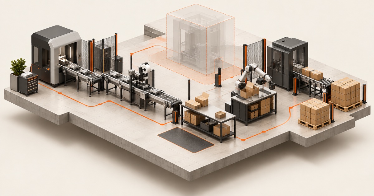
An extra machine is arriving next month. There is space for it on the factory drawing. But can an operator load it? Can maintenance open its service panel? Where will unfinished parts wait? And will adding the machine actually increase output, or simply move the queue somewhere else?
This is where 3D in manufacturing becomes useful: it helps a team examine a decision before committing equipment, material, labour, and floor space.
AI creates an opportunity to build software around those decisions. A practical application can turn a request into a proposed layout, generate a variation of an approved part, or prepare a comparison for an engineer. Its value depends on the quality of the underlying measurements, rules, and engineering tools.
This guide explains the workflows factories can use and a concrete way to build an AI-assisted layout planner. The implementation and numerical examples below are proposed designs and illustrative calculations, not results from a deployed customer project.
What 3D in manufacturing actually means
Several different deliverables get described as “3D.” Understanding the differences helps you build the right product and explain what a customer is buying.
A visual model explains appearance and space
A 3D scene can show a machine, a workstation, or an entire production area. People can rotate it, inspect it, and discuss a proposed change. The scene may use simplified geometry because a layout discussion does not require every screw to be visible.
For an early planning tool, represent equipment as measured blocks, with separate zones for operation and maintenance. Label the model’s accuracy and purpose so nobody mistakes an approximate envelope for a surveyed installation drawing.
A CAD model defines geometry
Computer-aided design models support engineering work on parts and assemblies. A parametric model lets a designer change named inputs, such as width or hole spacing, and regenerate the geometry.
For example, CadQuery creates parametric CAD models through Python. This provides a useful interface for automation: software can supply validated parameters to a reviewed modelling script.
A simulation represents behaviour
Showing a conveyor moving is an animation. Predicting production behaviour requires a model of processing times, arrival patterns, queues, resource availability, and operating rules.
Visual Components describes industrial workflows spanning factory layout, manufacturing simulation, robot programming, and virtual commissioning. These are distinct capabilities. A custom viewer should make clear which of them it actually implements.
A digital twin stays connected to its physical counterpart
Use the term carefully. For the purposes of a factory project, specify what real equipment or process is represented, which data updates it, how often it updates, and what decisions it supports. A static scene alone does not establish those capabilities.
NIST’s work on digital-twin credibility stresses verification, validation, and uncertainty assessment throughout the model’s life. Attractive graphics do not establish predictive accuracy.
Factory problems worth building for
Start with a decision that already creates work, delays, or costly revisions. The following use cases describe potential products; each needs discovery with an actual manufacturer before you commit to building it.
1. Planning a machine installation or line expansion
The trigger is concrete: equipment is being added, a production cell is moving, or a new product needs floor space.
Build a planning workspace where an engineer places equipment in a measured area and compares options. Include the operating envelope, maintenance access, material staging, and movement routes. AI can interpret requests and draft alternative arrangements within known constraints.
The deliverable is an editable layout plus a record of checks and unresolved assumptions. Measure time to review a layout and the number of late changes discovered during installation planning.
2. Reducing repetitive CAD work
Some product families vary within a controlled design space: dimensions, mounting patterns, or approved component combinations change while the underlying design logic stays similar.
Build a configurator around a manufacturer’s reviewed templates. A user supplies requirements; the system identifies missing information, validates the inputs, and generates a candidate model for review.
Keep the manufacturer’s design limits explicit. An AI model should not invent allowable loads, materials, tolerances, or fabrication rules. Measure engineering preparation time and correction rates against the existing process.
3. Preparing fixtures and assembly aids
A fixture locates or holds a workpiece during an operation. A useful project might help engineers prepare variations of an assembly nest or a positioning aid for a changing product family.
Begin with the part geometry, contact surfaces, loading direction, and operating conditions. Generate a candidate from a reviewed template, then prototype and evaluate it physically. Materials, wear, temperature, and clamping behaviour belong in the engineering review.
Treat automatic geometry generation as one stage of the workflow. A model that exports successfully has not yet demonstrated that it works on the line.
4. Comparing production scenarios
A manager may need to know whether another station, a larger buffer, or a different operator allocation will help meet demand.
Build a scenario interface around a validated simulation engine. Let users change controlled assumptions and compare outputs with the baseline. Display the underlying settings beside the result so the team can inspect why a scenario changed.
The commercial deliverable is a decision-support workflow with traceable assumptions. Its usefulness depends on whether the baseline reproduces observed behaviour closely enough for the question being asked.
5. Creating assembly and maintenance instructions
An approved assembly model can become a navigable set of work instructions: isolate a component, show its orientation, and display the relevant approved step.
AI can help draft explanations or organise existing documentation. The actual operation sequence, torque values, inspection points, and revision status must come from controlled engineering information.
A sensible first scope is one assembly and one audience. Test whether users complete the task correctly and whether the instructions remain consistent when the design changes.
Build a first product: an AI-assisted layout planner
Consider a hypothetical manufacturer planning a packaging cell with an inspection station, labeller, packing bench, and pallet area.
Its first application should answer a narrow question: Which candidate arrangement fits the available area and satisfies the planning rules we have recorded?
Start with one cell and measured equipment envelopes. Add dynamic throughput analysis only after you have useful operating data. This keeps the first deliverable understandable and gives the factory something it can review directly.
Step 1: Collect the inputs with the factory team
Ask for a dimensioned floor plan, equipment specifications, and a walkthrough with the person responsible for the area. Identify:
- Walls, columns, doors, ceiling restrictions, and fixed utilities.
- Equipment dimensions and orientation.
- Loading, unloading, operator, and maintenance access zones.
- Material entry points, staging areas, and finished-goods destinations.
- Approved movement routes and site-specific restrictions.
- Which machines can move and which positions are fixed.
Record the source and verification status of each measurement. If a drawing and the physical area disagree, the application should surface the conflict rather than silently choosing one.
Step 2: Define a consistent coordinate system
Choose one unit system and document the origin and axes. For example, use metres, set the floor origin at a surveyed corner, and make Z the vertical axis.
Each equipment record should separate its visual asset from its planning geometry. A detailed manufacturer model may look accurate but omit the space needed to open a door or replace a component.
An illustrative record could look like this:
{
  "id": "inspection-01",
  "units": "metres",
  "position": { "x": 4.0, "y": 2.5, "z": 0.0 },
  "rotationDegrees": 90,
  "equipmentSize": { "x": 1.8, "y": 1.2, "z": 1.6 },
  "accessZones": [
    {
      "side": "service-panel",
      "requiredDepth": 1.0,
      "source": "illustrative input; replace with verified requirement"
    }
  ],
  "fixedPosition": false,
  "verificationStatus": "pending"
}
These dimensions are demonstration inputs, not equipment recommendations. In the product, every required clearance should come from an identified source or an authorised site decision.
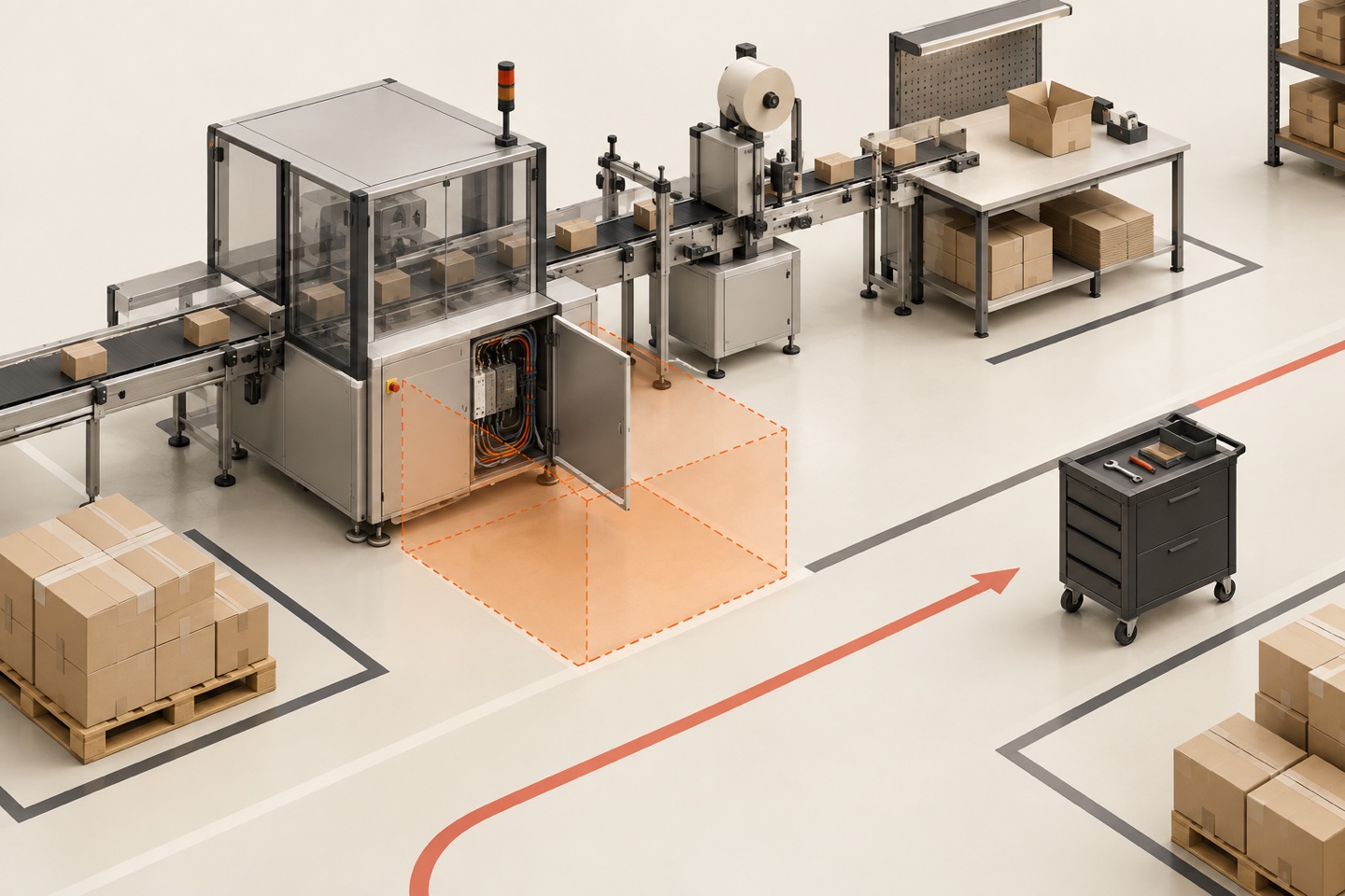
AI-generated conceptual illustration: access zones are separate from machine footprints; actual clearances require verified site data.
Step 3: Make the basic viewer useful before adding AI
Build a workspace with a top-down plan and a rotatable 3D view. Users should be able to select equipment, inspect its dimensions, move it numerically, and toggle access zones.
For a browser implementation, Three.js provides a glTF loader for displaying compatible 3D assets. Keep the measured layout records authoritative; a mesh is the visual representation of those records.
Include undo, save, revision names, and side-by-side scenario comparison. Those features make the tool useful during an actual engineering meeting.
Step 4: Turn natural language into a proposed change
The user might ask: “Move packing closer to inspection and leave the service access clear.”
Send the relevant layout data and permitted actions to the language model. Ask it to return structured proposals such as moveEquipment, rotateEquipment, or createScenario, with equipment IDs and numeric values.
If “closer” conflicts with a fixed asset or an unknown requirement, request clarification. Show the proposed change on a copy of the layout, together with its interpretation of the request, before the user accepts it.
Step 5: Validate changes with deterministic code
Use application code to check dimensions and geometry. Define checks for the scoped planning problem:
- Equipment outside the available floor boundary.
- Overlapping equipment footprints or restricted access zones.
- Changes to assets marked as fixed.
- Invalid units, missing dimensions, or impossible coordinates.
- Obstructed routes represented in the model.
For an initial prototype, simple rectangular envelopes can expose obvious conflicts. Irregular shapes, rotating machinery, and vehicle manoeuvres need richer geometry and movement analysis. Display the coverage of the checks so “no conflicts found” is not interpreted as comprehensive installation approval.
Step 6: Compare alternatives using transparent calculations
Begin with metrics you can calculate from the available data: occupied area, route length along permitted paths, and unresolved clearance conflicts.
For example, suppose a verified route between two stations falls from 18 metres to 11 metres. At an illustrative 120 one-way transfers per shift, the difference is:
(18 - 11) metres × 120 transfers = 840 metres per shiftThis is a travel-distance estimate. It does not directly establish labour savings or increased output. Loading time, return journeys, congestion, and whether walking constrains production still matter. Keep those assumptions visible instead of converting the number into an unsupported ROI claim.
Step 7: Add simulation when the decision requires it
To estimate throughput, collect observed processing times, changeovers, downtime, buffer capacities, shift schedules, resource-sharing rules, and product mix. Represent variability where it affects the outcome.
First reproduce the current arrangement and compare its outputs with observed production. Investigate discrepancies before evaluating alternatives. For stochastic models, compare repeated runs and the spread of results, not a single attractive number.
An AI layer can help users define scenarios and explain reported outputs. The simulation engine should calculate those outputs. Keep model versions and assumptions attached to every comparison.
Step 8: Produce a reviewable handoff
Save the chosen scenario with dimensions, equipment IDs, revision history, check results, and open issues. Include who reviewed it and what they approved.
Distinguish “layout reviewed for this planning exercise” from “released for physical installation.” If downstream teams need CAD, drawings, or a report, agree on the required formats and level of detail before the pilot starts.
That handoff is part of the product. A viewer that cannot preserve the team’s decision creates another round of manual documentation.
How to structure the application
The following is a proposed architecture, not a requirement to replace a factory’s existing systems. Keep established CAD, simulation, and document-control software where it already serves the team.
Interface and project records
Use a web interface for the 3D viewer, input forms, comparisons, and review actions. Store projects, equipment definitions, scenarios, permissions, and approvals in a database. Store uploaded models and exports in object storage, linked to immutable revision records.
Keep site-specific rules separate from application code where practical. A changed clearance requirement should be reviewable and should identify which saved scenarios need to be checked again.
Geometry and calculation services
Run geometry validation and calculations independently from the chat layer. Long-running CAD or simulation jobs should return job IDs and explicit progress or failure states.
Use a controlled catalogue of supported operations for production. If an experimental workflow executes generated code, isolate it with restricted files, network access, execution time, and resource limits. Customer drawings and engineering records should not become accessible to unrelated jobs.
AI orchestration
Give the AI access to the specific project records and operations needed for the request. Its job is to interpret intent, identify missing inputs, propose allowed actions, and explain actual calculation results.
Log the request, proposed actions, checks, and accepted revision. Reject fabricated equipment IDs and unsupported operations. When required data is absent, the correct product behaviour is to show what is missing.
Extending the workflow into CAD automation
Once a constrained application works, a related product could generate variations of an approved part or fixture template. The workflow is: collect parameters, validate them, regenerate geometry, inspect the result, and send it for engineering review.
CadQuery supports several import and export formats. STEP is useful for geometry exchange; mesh formats serve different downstream purposes. Preserve the source script and input parameters because exported geometry does not automatically preserve the original parametric design history.
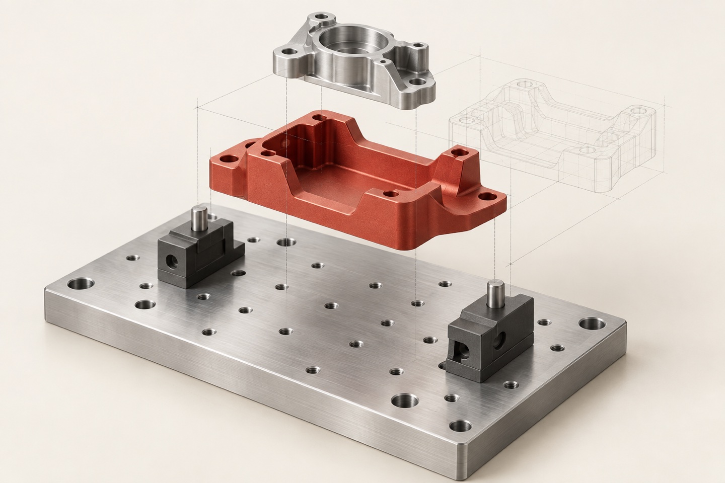
AI-generated conceptual illustration, not an engineering-approved fixture or fabrication drawing.
Separate design generation from manufacturing preparation
Agree on the deliverable before promising “manufacturing-ready” output. The customer may need toleranced drawings, material specifications, assembly information, or machine-specific preparation in addition to geometry.
Autodesk’s additive-manufacturing training illustrates this distinction: preparation includes machine selection, material and motion settings, supports, validation, and code export. A geometry file is one input into that process.
Treat optimisation as an engineering study
Generative design is another possible extension, but it requires defined objectives and constraints. Autodesk describes generative design for manufacturing in terms of exploring designs against requirements and evaluating their performance and manufacturability.
For a custom application, the engineer should define loads, preserved geometry, allowed materials, and manufacturing constraints. AI can assist the workflow around the study; a conversational claim that a part is stronger is not an engineering result.
Turn the prototype into a paid manufacturing project
Choose a buyer with an active decision: a plant engineer preparing an expansion, a production manager considering a cell change, or a design team repeating the same configuration work.
Ask to see the last time they completed that task. Identify the inputs, revisions, waiting periods, approval path, and final deliverable. This reveals whether the need is a viewer, data cleanup, CAD automation, simulation, or simply better integration between existing tools.
Scope a pilot around one measurable outcome
A proposed pilot could cover one production cell, its verified equipment catalogue, the baseline arrangement, and three alternatives. Deliver the comparison workspace, a reviewed report, and a list of remaining engineering questions.
Define acceptance criteria in advance: the team can reproduce the baseline, review changes, trace the input measurements, and export the agreed handoff. Expansion into other cells should follow evidence from that pilot.
Measure value without double counting
Compare the same task before and after implementation. Useful measures include preparation time, review time, corrections, and elapsed time to a decision.
As an illustrative calculation, 20 configuration requests a month saving 30 minutes each create 10 hours of potential capacity. That capacity is not automatically a cash saving. Establish how the team will use it, and account for data preparation, software operation, and review costs.
Price against a defined scope and support obligation. The defensible service includes reliable inputs, working integrations, validated checks, and adoption by the team.
Use coding agents to build the surrounding software
Coding agents can help implement the interface, schema validation, job handling, tests, and export workflow. Give each task a concrete input, expected behaviour, and acceptance criteria.
For example: “Implement equipment placement using metre-based coordinates. Reject movement of fixed assets. Add a regression check for a rotated rectangle crossing the floor boundary.” This is easier to evaluate than “build an AI factory.”
tellnova runs background coding agents in isolated git worktrees. It can support the software development work around this application; CAD validation and manufacturing expertise remain separate responsibilities. See the tellnova download page for the app and the tellnova blog for related development workflows.
Start with a factory decision you can verify
The opportunity in AI and 3D manufacturing is to make a specific engineering workflow easier to complete and review. A measured layout, a controlled configuration tool, or a well-scoped scenario comparison can be a useful starting point.
Pick one factory team and one recurring decision. Build with its actual inputs, preserve its engineering rules, and demonstrate the complete path to an approved handoff. That gives a buyer something concrete to evaluate and gives a builder a product whose value can be measured.
Related workflow
For the software that runs these jobs, see observability setup: alerts before outages.